
Abstract
Retrofitting a flexographic press with a mercury UV dryer can expand ink and coating options, but it also increases thermal load on the web. Polyolefin films such as polyethylene and polypropylene are sensitive to heat, tension, and uneven cooling. A chill roll system must therefore be sized from the complete process balance, not from web width alone. Lamp power, exposure time, reflected radiation, web speed, film thickness, ink laydown, and cooling-water conditions all affect web temperature. This article presents an engineering method for integrating mercury UV curing with chill rolls on flexographic presses. It covers thermal calculations, roll geometry, UV dose, ink compatibility, web handling, validation tests, and troubleshooting for stable production.
Introduction
The search intent behind “Flexo Mercury UV Dryer Integration: Sizing Chill Rolls for Heat-Sensitive Polyolefin Films” is strongly practical. Press owners and OEM engineers want to know how to combine a mercury UV lamp with cooling hardware before processing thin PE or PP films. They need a method for selecting roll diameter, cooling capacity, wrap angle, and control logic without causing shrinkage, curl, registration drift, or blocking.
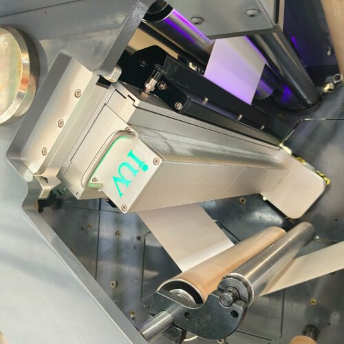
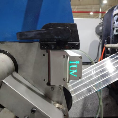
Mercury UV dryers emit a broad spectrum that can cure many conventional UV flexographic inks, varnishes, and adhesives. They also produce infrared energy and heat through the lamp body, reflector, exhaust stream, and surrounding press structure. Polyolefin films do not absorb this heat in the same way as paper. Their dimensions and stiffness can change when the web temperature rises or varies across the width.
A reliable installation treats the UV dryer, chill rolls, ink system, and web path as one thermal process. The goal is to deliver the required UV dose while keeping the film within a controlled temperature range at every critical point.
Define the Polyolefin Film and Job Range
Start with a material map rather than a single sample roll. Record film type, thickness, density, surface treatment, coating, maximum web width, roll length, and storage condition. Cast and blown films can respond differently to heat and tension. Biaxially oriented films may show stronger dimensional changes when the process approaches their thermal relaxation range.
List the full job envelope. Include minimum and maximum press speeds, ink coverage, white or opaque layers, metallic effects, overprint varnish, adhesive coating, and the number of UV stations. A transparent film with a light process image may create little thermal load. A white flood coat followed by a varnish can absorb and reflect energy differently, increasing both cure demand and web heating.
Also identify whether the film is corona-treated or primer-coated. Surface treatment affects ink wetting and adhesion, but it can decline during storage or after excessive heat exposure. The retrofit specification should protect the film surface while providing enough cure energy for the selected ink system.
Quantify the Mercury UV Dryer Heat Load
A mercury lamp must be evaluated by delivered UV energy and rejected heat. Electrical input is not equal to useful curing energy. Some energy leaves through the exhaust, some reaches the web as ultraviolet radiation, and the remainder enters the press frame, air stream, and film as heat.
Estimate the web heat load from lamp exposure, web speed, lamp-to-web distance, reflector condition, and the number of active lamps. Use the worst-case production recipe, not an idle lamp setting. A higher speed reduces exposure time, but operators may raise lamp power to maintain dose. That adjustment can increase thermal load even when the production rate is unchanged.
Measure web temperature before the lamp, immediately after the lamp, and after the first cooling roll. Repeat the measurements at the operator side, centre, and drive side. Cross-web differences often reveal reflector contamination, uneven exhaust, lamp ageing, or inadequate water flow through the roll.
Temperature data should be recorded with press speed and lamp settings. A temperature value without process conditions cannot be used to size cooling equipment or diagnose later drift.
Size Chill Rolls From Contact and Heat Transfer
Chill-roll sizing depends on more than face width. Roll diameter, wall construction, internal water passages, wrap angle, contact length, surface finish, and water temperature determine how quickly heat leaves the web.
A larger diameter can provide a longer contact path at the same wrap angle. Longer contact gives the film more time to transfer heat into the roll surface. However, a large roll also adds inertia and may require more frame space. The correct size must fit the press layout while maintaining stable web tension and bearing loads.
The cooling roll should have uniform temperature across the working width. Internal flow must avoid stagnant zones that create hot bands. Specify the inlet and outlet arrangement, flow direction, pressure drop, and allowable temperature difference between water entering and leaving the roll. If the roll cools unevenly, the film can develop cross-web shrinkage or tension variation.
Roll surface finish also matters. A damaged or contaminated surface can mark a freshly cured film. The surface should provide the required release and friction characteristics without trapping residual ink or varnish.
Select the Location and Wrap Angle Carefully
The first chill roll after the mercury UV dryer usually has the greatest thermal duty. Placing it too far from the lamp allows the film to remain hot while tension is still changing. Placing it too close can expose the roll coating, bearings, or seals to excessive radiant heat.
Use a short, controlled path between lamp exit and cooling contact. Shield the roll from direct infrared radiation where practical. A reflective barrier can reduce radiant heating of the roll, but it must not disturb lamp exhaust or create an unsafe light path.
Wrap angle controls contact time and traction. Too little wrap may remove insufficient heat. Too much wrap can increase tension, slip, or blocking risk if the surface is still soft. The preferred angle depends on speed, film stiffness, surface friction, and the required cooling duty. Validate the angle with temperature and tension measurements rather than selecting it from a generic press layout.
Match Lamp Output to Ink and Film Chemistry
The broad spectrum of a mercury UV dryer can support many UV flexographic formulations, but each ink and varnish still has its own dose and spectral response. Pigmented whites, opaque colors, and high-build coatings may need more effective energy than transparent process inks.
Request cure guidance for the exact ink series, photoinitiator package, and film construction. Confirm whether the formulation is intended for mercury lamps and whether it requires nitrogen assistance or a specific lamp spectrum. Do not assume that a surface that feels dry has achieved full through-cure.
Ink film thickness is influenced by anilox volume, plate relief, doctor-blade settings, viscosity, and press speed. A high-volume anilox can place a heavy layer on a low-absorbency film. That layer may require more dose and may retain more heat during the cooling path. The process window should link anilox selection with lamp settings and chill-roll temperature.
Control Oxygen Inhibition and Surface Cure
Oxygen inhibition can leave the outer surface of a UV ink slightly tacky, even when the film cures well below the surface. This condition is common with thin films that carry a smooth, non-porous surface. It can cause blocking, dust pickup, poor rewinding, or scuff marks.
Check whether the ink system uses an amine synergist, a surface additive, an inerting hood, or a final varnish designed for the selected lamp. If an inerting system is installed, verify gas flow, seal condition, oxygen concentration, and web clearance. A leak at the hood entrance can create a narrow tacky band that appears to be a chill-roll problem.
Cooling cannot correct oxygen inhibition. Lowering roll temperature may harden the film temporarily while leaving the chemistry under-cured. Cure verification must therefore include surface rub, tape adhesion, blocking, and solvent-resistance checks where relevant.
Design the Cooling-Water System for Stable Operation
Chill-roll performance depends on water temperature, flow, pressure, cleanliness, and control response. A cold-water setpoint alone does not guarantee stable film temperature. If flow falls during a long run, roll temperature can rise while the operator sees no immediate change in the lamp display.
Install flow and temperature monitoring on the critical roll circuit. Record inlet temperature, outlet temperature, flow rate, and alarm status with the press recipe. Water should be filtered to protect narrow internal passages. Corrosion, scale, and biological growth can reduce heat transfer and create uneven cooling.
The control system should coordinate lamp enable, web speed, water flow, and emergency stops. If cooling is lost, the press should reduce lamp output or stop the UV dryer according to the risk assessment. Manual intervention alone is not sufficient for a high-speed flexographic line.
Protect Web Tension and Registration
Heat changes film modulus and length. A web that exits the lamp with a temperature gradient can change register before the next print unit or converting station. Cooling rolls must remove heat without creating a sudden traction change.
Review nip pressure, draw settings, dancer position, and edge guiding around the dryer. A high-friction chill roll can pull the web and alter longitudinal register. A roll that is too smooth or too warm can permit slip, producing lateral movement and unstable print-to-print alignment.
Measure registration at operating speed after the machine reaches thermal equilibrium. Test during acceleration, steady production, and deceleration. Polyolefin films can behave differently during these transitions because tension and temperature do not change at the same rate.
Validate With a Structured Acceptance Test
The retrofit should include a written test plan before mechanical work begins. Use the thinnest and most heat-sensitive film, the heaviest ink coverage, and the highest intended speed. Include a control sample printed without UV exposure if the process allows safe comparison.
Record lamp power, measured irradiance, web speed, film temperature, chill-roll inlet and outlet conditions, web tension, and print registration. Inspect the film for shrinkage, edge wave, curl, wrinkles, blocking, gloss variation, and surface tack. Check adhesion after the film has cooled and again after a defined conditioning period.
A pass condition should include both cure and dimensional stability. A film that passes a rub test but loses register during lamination is not a successful process. Likewise, a dimensionally stable web with incomplete cure will fail in rewinding or customer use.
Troubleshoot Common Defects by Location
A hot centre band usually points to cross-web cooling imbalance, blocked internal passages, reflector distortion, or uneven lamp exhaust. A hot edge can indicate excessive edge radiation, poor water distribution, or a web path that places the edge outside the effective roll contact.
Shrinkage that appears immediately after the lamp suggests excessive radiant or convective heat. Shrinkage that develops after the chill roll may indicate inadequate cooling capacity, warm recirculated water, or heat retained in a heavy ink layer.
Tack limited to printed areas often indicates insufficient dose, oxygen inhibition, or excessive ink film thickness. Tack across the entire web may indicate lamp output loss, a disabled lamp bank, a dirty quartz window, or a control signal that is not enabling full power.
Wrinkles near the first chill roll should be checked against wrap angle, nip pressure, roll parallelism, and tension draw. Do not increase cooling pressure as a first response. Excessive nip force can create a new defect while masking the original thermal imbalance.
Plan Maintenance Around Thermal Performance
Mercury UV dryers require regular inspection of lamps, reflectors, quartz windows, exhaust filters, and cooling components. Contamination changes the optical path and can reduce delivered irradiance. A lamp that still ignites may no longer provide the same cure energy at the web.
Measure output at the web plane on a defined schedule. Compare centre and edge readings, and trend them against lamp hours and cleaning history. Inspect chill-roll water flow and temperature at the same time. Coordinating optical and thermal maintenance helps identify whether a defect comes from curing loss or cooling drift.
Keep approved settings for each film and job family. Operators should know the permitted range for lamp power, speed, water temperature, and tension. Recipe control limits unnecessary adjustments that could push a heat-sensitive polyolefin film outside its stable process window.
Conclusion
Integrating a mercury UV dryer into a flexographic press for polyolefin films requires a complete thermal and curing assessment. Chill rolls must be sized from heat load, contact time, water flow, roll geometry, and web behavior. Lamp spectrum, ink chemistry, anilox laydown, oxygen control, tension, and delivery conditions must be validated together.
A sound retrofit provides measured UV dose and controlled web temperature at production speed. It also gives operators clear alarms, repeatable recipes, and location-based troubleshooting methods. With those controls in place, heat-sensitive PE and PP films can run through mercury UV flexographic curing without sacrificing adhesion, register, or converting performance.