Abstract
Integrating UV LED curing equipment with a delam/relam unit requires control of two separated web paths and an exposed adhesive surface. Lamp placement must support ink cure before relamination while preserving adhesive performance, liner release, and print registration. Available installation space alone cannot determine a suitable configuration. Engineers must also evaluate the printed surface, spectral compatibility, web support, local tension, thermal exposure, and the first contact point after printing. A practical integration method begins by mapping the separated label construction, then assigning a curing position to each printed layer. Qualification must extend through relamination, die-cutting, dispensing, and final label application.
Introduction
A delam/relam unit temporarily separates pressure-sensitive label face stock from its release liner. The separated paths provide access for adhesive-side printing, adhesive deadening, liner printing, or other specialized operations. The webs then reunite at a controlled nip before further converting.
UV LED curing equipment for narrow-web presses must fit this sequence without compromising either web. A lamp can deliver adequate output yet produce an unsuitable process if uncured ink touches a roller before exposure. Similarly, a successful ink rub test does not establish that the pressure-sensitive adhesive retains its required tack or release behavior.
The central engineering task is to coordinate curing with separation and reunion. Each lamp needs a defined target surface, a stable working distance, and enough exposure before that surface reaches the next contact point.
Identify the Surface Exposed by Delamination
Standard delamination normally leaves the pressure-sensitive adhesive on the face stock and exposes the silicone release surface of the liner. This distinction determines ink selection and lamp orientation. Printing on the adhesive side is different from printing directly on bare face material.
Record which surface receives each deposit. An adhesive-side image, a patterned deadener, and a liner-side message perform different functions. Their formulations and acceptance criteria should therefore be specified separately.
If the intended process requires printing on bare face stock beneath the adhesive, simple delamination may not provide that access. The construction or manufacturing route must support it. This should be resolved before designing lamp brackets or allocating print stations.
Liner printing also requires precise identification of the printed side. The liner back and its release-coated face have different surface properties. Conventional ink selection should not be assumed suitable for direct printing onto silicone release coatings.
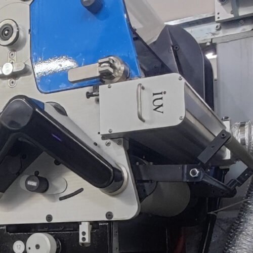
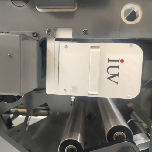
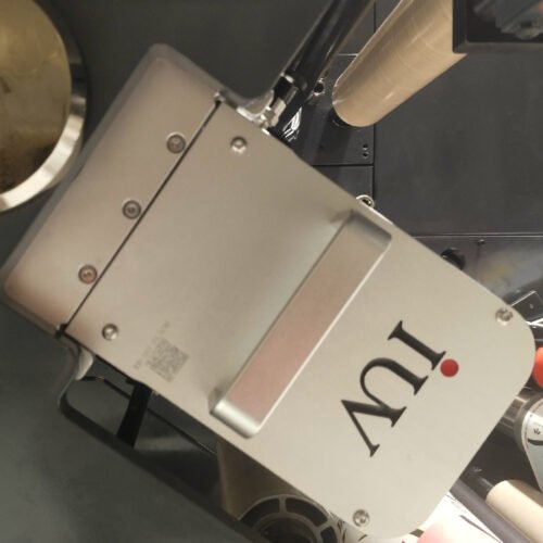
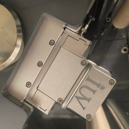
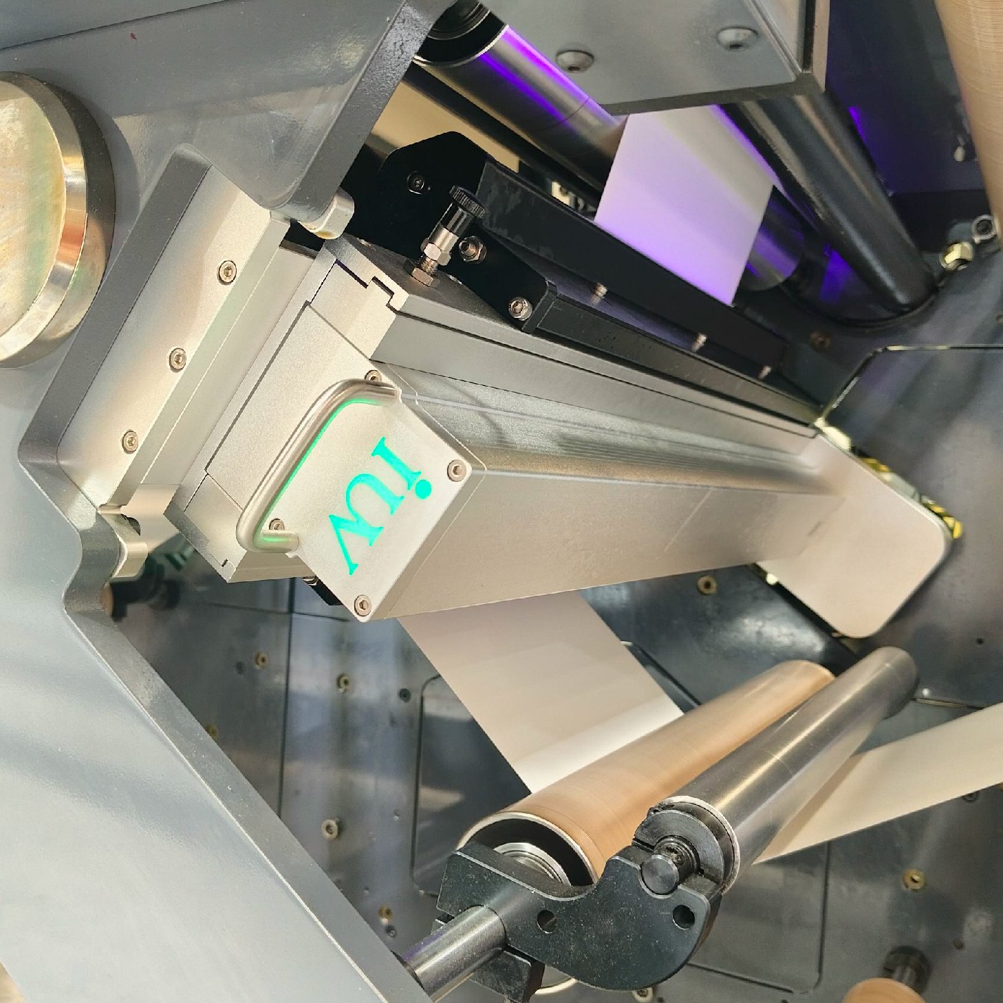
Position UV LED Curing Equipment for Narrow-Web Presses Before Critical Contact Points
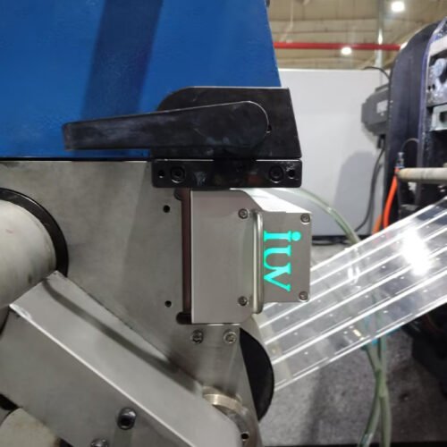
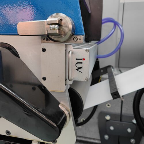
Place the curing module after deposition and before the printed surface contacts a roller, nip, or opposing web. Follow the actual threading path to locate that first contact. On compact delam/relam assemblies, an idler can sit between the print station and the apparent curing location.
For adhesive-side printing, the newly printed adhesive surface should face the lamp. Support rollers should contact an appropriate unprinted surface wherever the construction permits. Exposed adhesive touching an ordinary roller can cause transfer, contamination, and tension disturbances.
A direct optical path is generally easier to qualify than curing through the relaminated construction. After reunion, face stock, inks, adhesive, or liner may attenuate the wavelengths needed by the printed formulation. A visibly transparent film does not establish adequate UV transmission.
Where through-material curing is necessary, validate the complete optical stack at production thickness and coverage. Include tinted films, opaque graphics, primers, and material-lot variation in that assessment.
Control the Two Web Paths Independently
The face-stock branch and liner branch respond differently to tension once separated. Their stiffness, thickness, and dimensional stability may differ substantially. A tension setting that was acceptable for the complete label construction may distort one separated component.
Keep unsupported spans near the lamp short enough to maintain a repeatable exposure geometry. Flutter changes working distance and can create uneven cure. Excess tension may suppress flutter while stretching the face stock, creating a registration problem at relamination.
Review drive locations, idler alignment, web guides, and tension feedback on both branches. The lamp mounting should accommodate the approved web path without forcing a sharp wrap or an unnecessary change in direction.
Registration should be checked between front graphics and the adhesive-side image or deadened pattern. Measure it after relamination as well as before the nip. A pattern that appears aligned on the separated branch can shift when tension redistributes during reunion.
Match LED Spectrum to the Deposited Formulation
The ink or deadening coating must respond to the installed LED spectrum. A material described only as UV-curable may have been designed for a broad-spectrum mercury source. Compatibility with an LED module requires confirmation for the specific formulation and emission band.
Nominal wavelengths such as 385 nm or 395 nm identify different LED options, but neither is universally suitable. Photoinitiator response, pigment absorption, film thickness, and required surface properties determine the appropriate match.
Adhesive deadeners need particular care because their purpose is to alter tack in selected areas. Successful cure must produce the intended non-tacky region without spreading that effect into neighboring adhesive. Ink chemistry must likewise be suitable for its contact with the pressure-sensitive adhesive.
Do not treat lamp exposure as a method for correcting an incompatible material combination. A coating may become hard while still showing poor anchorage, undesirable interaction with the adhesive, or transfer during release.
Establish Irradiance and Exposure at the Separated Web
Measure irradiance at the actual printed surface, using instrumentation suitable for the LED spectrum and measurement geometry. A lamp-face rating cannot establish what reaches a moving web at the installed distance.
Radiant exposure, often called UV dose, combines intensity and exposure time. For a stable lamp profile, increasing web speed reduces the energy received by each area. Measurements should therefore be associated with speed, working distance, active width, and lamp setting.
Peak irradiance and total exposure should be considered together. Equal dose values obtained through different intensity profiles do not necessarily produce identical cure. Surface reactions, pigment loading, and oxygen inhibition can change the result.
Check the full printed width, including module junctions and outer lanes. A narrow weak band may become visible only when a deadening pattern or solid image crosses it. Where segmented output is available, confirm that active zones cover the printed area throughout normal lateral web movement.
Link Anilox Selection to Adhesive-Side Performance
Anilox selection determines the amount and uniformity of ink or coating transferred during flexographic printing. Nominal cell volume alone does not establish deposited thickness. Cell condition, doctoring, material rheology, and transfer efficiency also matter.
A heavier adhesive-side ink layer may improve visual density while increasing cure demand and changing local label thickness. At the relamination nip, that thickness variation can affect contact with the liner.
Deadening patterns require a balance between coverage and precision. Too little material may leave residual tack within the intended non-adhesive area. Excessive transfer may spread beyond the pattern boundary or create an uneven surface.
Qualify anilox, formulation, lamp setting, and line speed as a combined recipe. Inspect fine gaps and pattern edges as well as broad solids. These features often reveal transfer or cure limitations before a full-area test does.
Separate Ink Cure From Adhesive Function
A dry printed surface is only one acceptance condition. The pressure-sensitive adhesive must still provide its specified performance in the areas intended to remain active.
Retain an unprocessed control from the same label-stock lot. Compare it with material exposed to the approved lamp sequence without added ink, then with the complete printed construction. These comparisons help distinguish exposure effects from formulation interactions.
Assess tack, peel behavior, adhesive transfer, and release from the liner using consistent methods and conditioning. The required tests depend on the label application. A removable promotional label and a permanent industrial label should not share an assumed acceptance threshold.
Patterned adhesive deadening also needs application testing. Verify that active adhesive areas hold the label while the deadened areas behave as intended during opening, peeling, or handling.
Manage Oxygen Exposure and Temperature Before Relamination
The exposed printed surface cures in air unless the system includes an engineered inerting arrangement. For free-radical UV formulations, oxygen can interfere with surface cure. Persistent surface tack must be investigated alongside spectrum, irradiance, and deposited thickness.
Relamination should not be used to conceal an inadequately cured surface. Bringing the liner back into contact can transfer material or trap a weak layer. The required cure state should be reached before reunion unless a specifically validated process calls for another sequence.
LED systems still require thermal management. Absorbed radiation, polymerization heat, and surrounding equipment can raise the temperature of the separated construction. Lamp cooling stabilizes the source but does not directly guarantee acceptable web temperature.
Measure temperature near the curing exit and before the relamination nip. On thin or transparent webs, verify that the measurement method reads the intended surface. Maintain cooling conditions that also avoid condensation on rolls or web-contact components.
Tune the Relamination Nip After Cure Is Established
The relamination nip reunites the branches and controls contact between adhesive and liner. Pressure, roll alignment, surface condition, speed matching, and temperature all influence the result.
Set the nip to achieve uniform reunion without unnecessary compression. Excessive pressure cannot correct under-cure or chemical incompatibility. It may instead increase adhesive squeeze, marking, or distortion around heavily printed regions.
Inspect for bubbles, wrinkles, localized silvering, and changing release behavior. Relamination defects can arise from differential tension or trapped air even when curing is adequate. Conversely, material transfer at the nip may indicate a weak deposited layer.
Repeat release checks after a defined storage period. Pressure and time in the finished roll can expose problems that are absent immediately after relamination.
Integrate Controls Around Web Movement and Lamp Readiness
Lamp enable logic should account for actual press movement, the selected threading configuration, cooling status, and required guards. A recipe for a bypassed delam/relam unit should not automatically reuse the lamp settings for adhesive-side printing.
Coordinate output with the validated speed range. At low speed, maintaining a production-level setting can increase local exposure substantially. At high speed, the module may reach its output limit before delivering the required cure.
Record lamp faults with the affected production interval. If a required module loses output, the corresponding material needs identification and disposition. A downstream inspection camera may detect print defects, but it cannot establish chemical cure.
Include accessible cleaning and inspection positions in the mechanical design. Adhesive strings, paper dust, and coating contamination can accumulate near exposed web paths and reduce optical output.
Qualify the Complete Converting Route
Run acceptance trials with representative face stocks, liners, adhesive systems, and printed patterns. Include start-up, steady production, speed changes, and restart conditions. These transitions challenge both exposure control and branch registration.
Collect samples across the width and at several points in the run. Record lamp conditions, anilox identification, material lots, branch tensions, temperature, and nip settings. Evaluate the deposited layer before reunion where sampling can be performed safely.
Then test the finished construction through die-cutting, matrix stripping, rewinding, and dispensing. Examine whether adhesive-side deposits transfer to the liner or interfere with label release. Apply labels to the intended surface and evaluate the required function after conditioning.
Use failure location to guide correction. Smearing before the nip suggests premature contact or inadequate cure. Registration movement points toward branch mechanics. Changed release with sound print may require investigation of adhesive interaction, temperature, or nip conditions.
Conclusion
UV LED integration with delam/relam units depends on the condition of each separated surface before the webs reunite. Lamp modules need a stable optical path, sufficient exposure, and a location ahead of critical contact points.
A qualified process links formulation compatibility, anilox transfer, independent web tension, temperature, and relamination settings. Acceptance extends beyond ink dryness to adhesive function, liner release, registration, and final dispensing. Those combined checks provide a defensible operating window for specialized narrow-web label production.