Abstract
Retrofitting a flexographic press with UV LED curing systems involves more than replacing conventional UV lamps with LED units. The electrical supply, control architecture, cooling circuit, installation space, and production process must work together. Poor integration can lead to unstable curing, overheating, electrical faults, or unexpected press downtime. These risks become more significant on narrow-web label presses, where installation space is limited and production speeds are high. This article examines the main engineering considerations when integrating UV LED curing equipment into an existing flexographic press. It focuses on electrical compatibility, power control, cooling design, heat management, and commissioning checks. The aim is to help press owners, OEMs, and engineers assess retrofit conditions before installation and achieve stable production after conversion.
Introduction
Flexographic printing is widely used for pressure-sensitive labels, shrink sleeves, flexible packaging, and other narrow-web applications. Many existing presses still use conventional mercury UV systems. As production requirements change, some printers consider upgrading to UV LED curing.
A UV LED retrofit can reduce energy consumption and simplify lamp operation. It can also provide more consistent curing conditions when the ink and curing system are correctly matched. However, an existing press was not necessarily designed for LED equipment. Its electrical cabinet, control signals, cooling capacity, and mechanical layout may require modification.
The main challenge is therefore system integration. The retrofit must fit the press architecture without compromising operator safety, printing quality, or production reliability. Electrical integration and thermal management should be assessed together because both influence the operating stability of the curing system.
Electrical Integration for Flexographic Press Retrofit
Assessing the Existing Press Electrical Architecture
Before selecting UV LED curing equipment, engineers should review the press electrical drawings and available power supply. The inspection should cover the incoming voltage, frequency, phase configuration, circuit protection, grounding, and available electrical capacity.
An existing mercury UV system may use a power supply designed for lamp ignition and operation. An LED curing system uses different power electronics and control requirements. The original lamp supply should not be assumed to be compatible with the new LED equipment.
The retrofit team should confirm the rated input requirements of the LED power supply. This includes voltage tolerance, current demand, peak load, and the requirements for protective devices. The available capacity must also account for other press components operating at the same time.
If the existing electrical cabinet has limited space, a separate cabinet may be more practical. This can simplify cable routing, improve maintenance access, and reduce interference with existing press controls. The final arrangement should follow the machine manufacturer’s electrical and safety requirements.
Power Supply Selection and Electrical Protection
The LED power supply is a critical part of the retrofit. It converts the incoming electrical supply into the power required by the LED modules. Its capacity must match the connected curing units and their operating conditions.
Engineers should check whether the power supply supports the required output level and control range. A unit operating continuously near its maximum capacity may have limited flexibility for future production changes. Adequate capacity also helps prevent unnecessary electrical stress.
Electrical protection should be reviewed before commissioning. Circuit breakers, fuses, overload protection, and emergency isolation must be suitable for the new equipment. Cable size should match the current rating, cable length, installation environment, and applicable electrical standards.
Grounding is equally important. Poor grounding can increase the risk of electrical interference and unstable control signals. All metal enclosures and relevant equipment parts should be connected according to the approved grounding design.
Integration with Press Speed and Control Signals
A flexographic press changes speed during startup, production, and shutdown. The UV LED system must respond appropriately to these operating conditions.
A common integration method is to connect the LED controller to the press speed signal. The curing output can then follow production speed according to the selected control strategy. This helps maintain suitable curing conditions when the press accelerates or slows down.
The control interface may use an encoder signal, digital input, or another agreed communication method. Compatibility should be confirmed before installation. Engineers should check the signal type, voltage level, wiring arrangement, and response requirements.
The system should also define what happens when the press stops. In many applications, the LED output should switch off or move to a safe standby condition when web movement stops. This prevents unnecessary exposure and reduces heat accumulation on stationary material.
Emergency stop integration requires particular attention. The LED curing system must respond correctly to the press safety circuit. The required shutdown behavior should be agreed with the press manufacturer and verified during commissioning.
Cable Routing and Electromagnetic Compatibility
Electrical installation is not only about connecting the power supply. Cable routing can affect signal stability, maintenance access, and operator safety.
Power cables and low-voltage control cables should be routed separately where the equipment design requires it. Long parallel runs between power and signal cables may increase the risk of electrical interference. Shielded cables and suitable grounding arrangements may be necessary for sensitive signals.
Cables should also be protected from mechanical damage, vibration, ink contamination, cleaning chemicals, and high temperatures. Flexographic presses contain moving components and frequently require access for cleaning. Cable routes must not interfere with web paths, impression adjustments, anilox roller changes, or routine maintenance.
Before installation, engineers should prepare a cable schedule and connection plan. Clear identification at both ends makes future troubleshooting easier. Any changes to the original press wiring should be documented.
Thermal Management of UV LED Curing Equipment
Why Cooling Design Matters
UV LED modules convert electrical energy into optical output and heat. Although LED curing generally produces less unwanted heat toward the substrate than conventional mercury UV systems, the LED modules still require effective heat removal.
Excessive module temperature can affect output stability and component service life. It may also trigger thermal protection and interrupt production. Cooling should therefore be treated as a core part of the retrofit design, not an optional accessory.
The required cooling method depends on LED power, module configuration, operating environment, and equipment specifications. Air-cooled systems may suit certain lower-power installations. Higher-power or compact curing arrangements may require water cooling to maintain stable operating temperatures.
The cooling system must be selected according to the LED manufacturer’s requirements. A cooling solution should not be judged only by its nominal capacity. Actual performance depends on flow, inlet temperature, pressure, heat exchange, and installation conditions.
Water-Cooled Systems: Flow, Temperature, and Pressure
Water cooling is common in high-power UV LED curing applications. It transfers heat away from the LED modules through internal cooling channels and a circulation system.
Before installation, engineers should confirm the chiller capacity and compatibility with the LED modules. The cooling circuit should provide the required flow rate and maintain the specified inlet temperature. Both insufficient flow and excessively high water temperature can reduce cooling performance.
Water pressure should also remain within the equipment’s permitted range. Excessive pressure may damage connections or cooling channels. Low pressure can reduce circulation and cause local overheating.
The water circuit should be checked for leaks before the LED system enters production. Hoses should be routed securely and kept away from sharp edges and moving parts. Connections must remain accessible for inspection and maintenance.
Water quality also matters. Deposits, corrosion, or contamination can reduce heat transfer and restrict flow. The recommended coolant and maintenance interval should follow the equipment manufacturer’s instructions. If antifreeze or other additives are required, their compatibility with the cooling components should be confirmed.
Chiller Installation and Ambient Conditions
The chiller location can influence cooling performance. A unit installed in a poorly ventilated area may draw in warm air and struggle to reject heat. This can become a problem in printing rooms with several heat-generating machines.
The chiller should have sufficient clearance around its air inlet and outlet. Its installation position should also allow convenient access for cleaning filters, checking connections, and performing routine maintenance.
Ambient temperature should be considered during system selection. A chiller that performs adequately in a cool workshop may have less capacity during hot summer conditions. Engineers should evaluate the expected operating environment rather than relying only on ideal laboratory conditions.
For water-cooled installations, the distance between the chiller and LED modules should also be considered. Long pipe runs, multiple bends, and unsuitable hose dimensions can affect circulation. The final pipe arrangement should follow the system design.
Heat Exposure Around the Printing Station
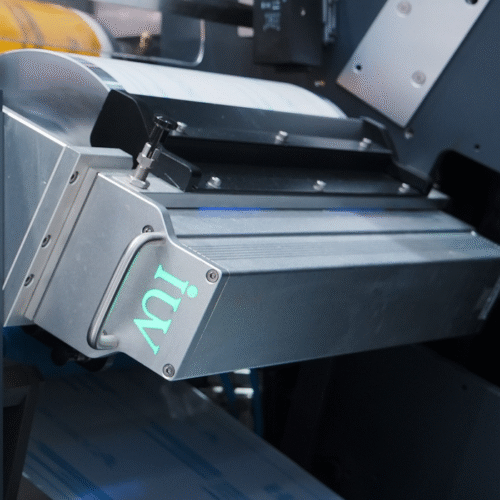
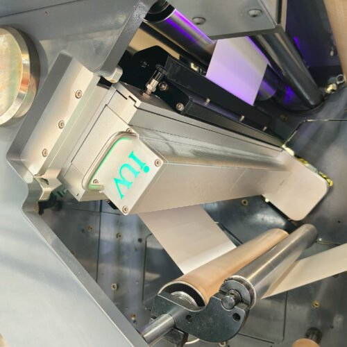
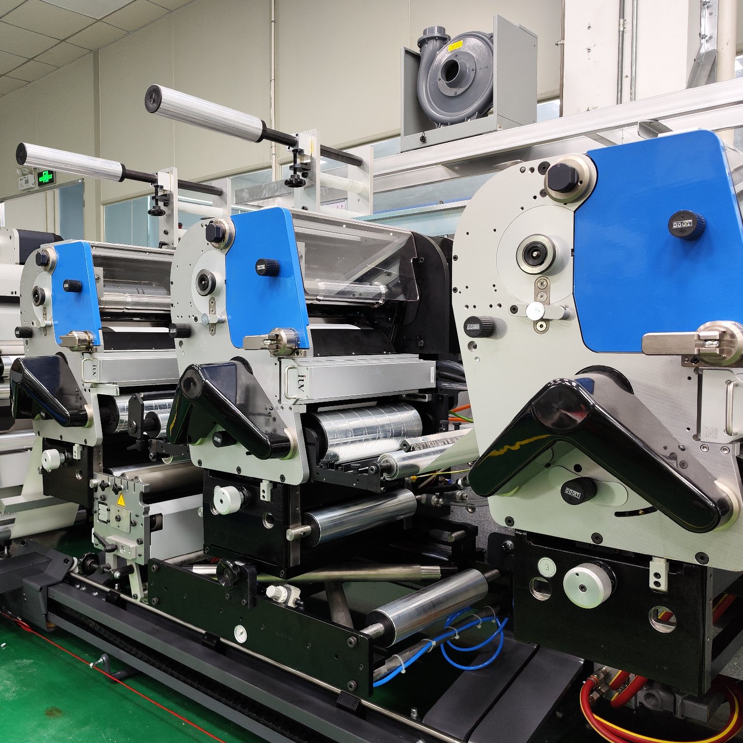
Thermal management also includes the surrounding press structure. The LED curing head is installed close to the printed web, rollers, guards, and other mechanical components. The retrofit should provide enough space for ventilation, cooling connections, and maintenance access.
The mounting structure must support the curing unit securely. Vibration or misalignment can affect the distance between the LED window and the substrate. A stable installation also helps maintain consistent curing conditions across the web width.
Although LED curing reduces direct infrared exposure compared with many conventional UV arrangements, the curing station still needs a suitable thermal assessment. Heat from motors, nearby dryers, the press environment, and the curing unit itself can accumulate in enclosed spaces.
Engineers should check whether the existing guards or covers restrict airflow. Any changes must preserve the machine’s safety requirements and prevent operator exposure to UV radiation.
Matching LED Output to Flexographic Printing Conditions
Wavelength and Ink Compatibility
Electrical and cooling integration cannot compensate for an unsuitable ink and LED combination. UV LED inks contain photoinitiators designed to respond to specific wavelength ranges.
Common UV LED curing wavelengths include 365 nm, 385 nm, 395 nm, and 405 nm. The correct selection depends on the ink formulation and the curing response required by the application. Engineers should confirm compatibility with the ink supplier rather than selecting a wavelength based only on the LED system specification.
The LED output should also provide sufficient irradiance at the working distance. Irradiance describes the intensity of UV radiation reaching the printed surface. It is different from total curing energy, which is influenced by exposure time and press speed.
A system may have a high rated output but still perform poorly if the installation distance or optical arrangement is unsuitable. The effective output should be checked at the actual production position.
Anilox Volume, Ink Film, and Curing Performance
Flexographic printing transfers ink through an anilox roller and printing plate. The anilox volume, cell structure, ink viscosity, and printing conditions influence the amount of ink deposited on the substrate.
A heavier ink film may require more effective UV exposure. This is especially relevant for solid areas, dense colors, opaque white, and certain specialty inks. The curing system must be evaluated under realistic print conditions.
The LED curing unit should cover the full web width. Uneven output across the curing area can result in differences in surface curing, adhesion, or resistance. Engineers should consider the actual printing width and the position of the printed image.
If the press uses multiple colors, curing performance should be checked at each relevant station. A stable result at one station does not automatically confirm that the entire printing sequence is suitable.
Press Speed and Production Stability
Production speed directly affects the exposure time available at the curing station. A press running faster gives the printed ink less time under the LED output. The system must provide suitable curing performance at the required production speed.
Testing should include normal operating speed and the highest speed expected for the job. Startup and speed changes should also be checked. If the LED output follows press speed, the control response must be stable and repeatable.
A retrofit should not be approved based only on a low-speed test. The final validation should use representative substrates, inks, print coverage, and production conditions. This provides a more realistic assessment of curing performance.
Substrate and Print Quality Considerations
Managing Heat-Sensitive Label Materials
Many label applications use thin films, including PE, PP, and PET. These materials can be sensitive to excessive heat or dimensional changes. Poor process control may cause web distortion, shrinkage, or registration problems.
UV LED curing generally reduces unwanted heat transfer to the substrate. However, the overall press environment still matters. Tension settings, drying equipment, ambient temperature, and mechanical contact can all influence web stability.
During commissioning, engineers should monitor the substrate after curing. Check for curling, deformation, changes in web tension, and registration movement. If defects appear, review the entire process rather than assuming the LED unit is the only cause.
Preventing Poor Adhesion and Incomplete Curing
Poor adhesion, surface tack, and weak rub resistance may indicate insufficient curing. However, these defects can also result from ink incompatibility, contamination, substrate treatment, or incorrect printing conditions.
Oxygen inhibition can affect the surface curing of some UV ink formulations. The issue may become more noticeable with certain ink chemistries or thin ink films. The ink supplier should confirm whether the formulation is suitable for the selected LED wavelength and curing conditions.
Testing should include practical quality checks. These may cover surface tack, adhesion, scratch resistance, rub resistance, and any application-specific requirements. For food-related or other regulated packaging, migration performance must be assessed through the appropriate testing and compliance process.
A low-migration claim should never be based on the curing unit alone. Ink formulation, substrate, coating, process conditions, and final packaging structure all contribute to compliance.
Maintaining Registration and Color Consistency
Stable curing helps maintain predictable printing conditions between color stations. Inadequate curing can allow ink to remain sensitive during subsequent printing or finishing operations. This may affect handling, surface quality, or downstream processing.
Excessive or poorly controlled curing conditions can also create process difficulties. The goal is not simply to maximize LED output. It is to achieve the required curing result while maintaining substrate stability and consistent print quality.
When investigating registration changes, engineers should check web tension, roller condition, substrate behavior, and press temperature. Curing output should be reviewed alongside these mechanical factors.
Retrofit Planning, Installation, and Commissioning
Confirming Mechanical Compatibility
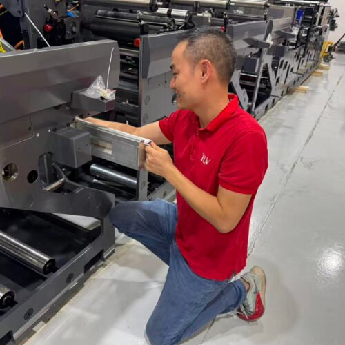
Before purchasing a UV LED system, the installation area should be measured. Important dimensions include the available mounting width, height, working distance, and access space.
The curing head must fit the press without obstructing operator access or routine maintenance. Engineers should also consider the position of guards, inspection windows, web guides, and existing drying equipment.
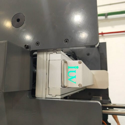
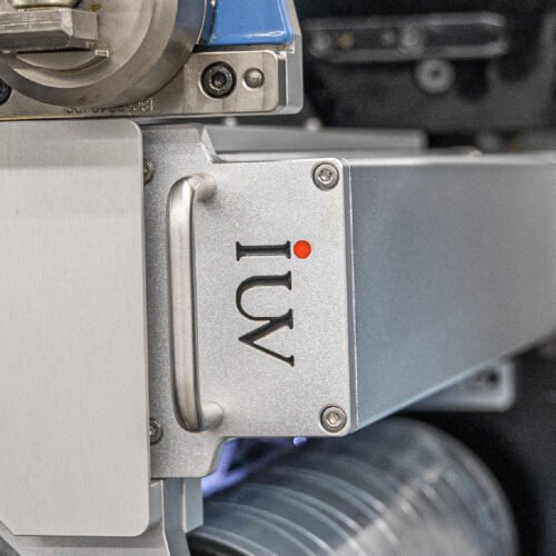
Mounting brackets should provide sufficient rigidity. If the original mercury lamp housing is reused, its structural condition and suitability must be checked. A housing designed for conventional lamps may not provide the correct mounting position or cooling arrangement for LED equipment.
Preparing an Integration Checklist
A retrofit project should have a clear technical checklist before installation. This reduces uncertainty and helps different teams coordinate their work.
The checklist should cover:
- Incoming voltage, frequency, phase, and available electrical capacity.
- Power supply rating and electrical protection.
- Grounding and cable routing.
- Press speed signal and control interface.
- Emergency stop and shutdown behavior.
- LED module mounting position and working distance.
- Cooling capacity, flow, pressure, and water temperature.
- Chiller location and ventilation.
- Ink wavelength compatibility and substrate requirements.
- Operator safety, guarding, and maintenance access.
The press manufacturer, LED system supplier, and end user should agree on the integration responsibilities. Any required modifications to the original machine should be documented.
Commissioning and Production Validation
Commissioning should begin with electrical and cooling checks. Confirm the wiring, grounding, protective devices, cooling connections, and controller settings before activating the LED modules.
The cooling circuit should operate within the specified conditions. Check for leaks, abnormal noise, unstable flow, or unexpected temperature changes. The LED system should also be tested at different output settings.
Next, verify the communication between the press and curing controller. Confirm that the LED output responds correctly to press startup, speed changes, normal stopping, and emergency stopping.
Production validation should use the actual ink and substrate combinations planned for the press. Test representative colors, solid areas, and demanding print jobs. Check curing quality at normal and maximum production speeds.
Record the operating conditions during the test. Useful information includes press speed, LED output setting, working distance, cooling temperature, and quality inspection results. These records provide a baseline for future maintenance and troubleshooting.
Maintenance and Troubleshooting After Retrofit
Electrical and Control System Inspection
After installation, electrical connections should be inspected according to the equipment maintenance schedule. Loose terminals, damaged cables, poor grounding, or contaminated connectors can cause unstable operation.
If the LED system fails to respond to press speed changes, check the encoder signal and control wiring first. Confirm that the controller receives the correct signal and that the configured response matches the press operation.
Unexpected shutdowns may be related to electrical protection, power supply faults, or thermal protection. Alarm records can help identify the cause. Operators should avoid repeatedly resetting the system without investigating the underlying issue.
Cooling System Maintenance
Cooling performance should be monitored during normal production. Check the chiller display, water flow, inlet temperature, and visible hose condition. Clean filters and heat exchanger surfaces according to the manufacturer’s recommendations.
If the LED module temperature rises unexpectedly, inspect the cooling circuit before changing the curing output. Possible causes include blocked filters, insufficient coolant, restricted hoses, poor ventilation, or chiller malfunction.
Water leakage requires immediate attention. The affected equipment should be isolated according to the approved safety procedure before repairs begin.
Common Quality Problems and Practical Checks
Incomplete curing should be investigated through a structured process. First, confirm that the ink is compatible with the LED wavelength. Then check output settings, working distance, press speed, and ink film conditions.
Uneven curing across the web may indicate inconsistent LED output, incorrect alignment, or unsuitable installation geometry. Inspect the curing head position and verify output across the working width.
Substrate deformation should prompt a review of press temperature, web tension, and nearby heat sources. Surface tack may require a closer look at ink chemistry, oxygen inhibition, and actual curing conditions.
A consistent troubleshooting record helps separate electrical, thermal, mechanical, and ink-related issues. This is especially useful on presses running several product types and substrates.
Conclusion
A successful flexographic press retrofit requires careful coordination between electrical integration, thermal management, and printing conditions. The LED power supply must match the press electrical architecture. Control signals must respond reliably to production speed and safety functions. Cooling capacity and installation conditions must keep LED modules within their specified operating range.
Ink compatibility, anilox volume, substrate sensitivity, and production speed also influence the final curing result. These factors should be validated using representative production jobs rather than theoretical settings alone.
For press owners and OEMs, a structured assessment before installation can reduce downtime and avoid costly modifications. With suitable system design, commissioning, and maintenance, UV LED curing equipment can be integrated into existing flexographic presses while supporting stable label production.