Abstract
An interdeck LED-UV retrofit can change how a sheetfed offset press handles ink trapping, setoff control, coating adhesion, and turnaround time. Its success depends on more than fitting curing heads between printing units. The installation must preserve gripper clearance, sheet transport, access to blankets and rollers, thermal stability, and the operating logic of the press. This article examines the engineering requirements for integrating interdeck LED curing into sheetfed offset press configurations. It focuses on the relationship between lamp position, UV offset ink chemistry, sheet path, cure energy, dampening behaviour, and production validation.
Introduction
UV LED offset printing retrofit projects are commonly evaluated by printers that need faster handling of UV inks, improved intermediate curing, or greater control over difficult substrates. In sheetfed offset production, interdeck curing is used between print units rather than only at the delivery. This allows selected ink layers to be pinned or partially cured before the sheet reaches the next unit.
The practical goal is not to cure every ink layer as strongly as possible. The goal is to achieve controlled ink stabilisation without disrupting trapping, sheet handling, registration, or the ink-water balance. The retrofit must work with the mechanical rhythm of the press and the chemical response of the ink system.
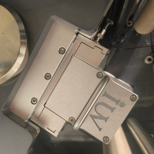
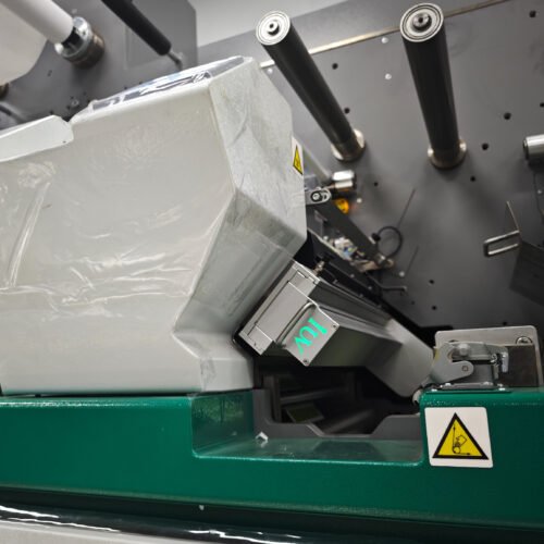
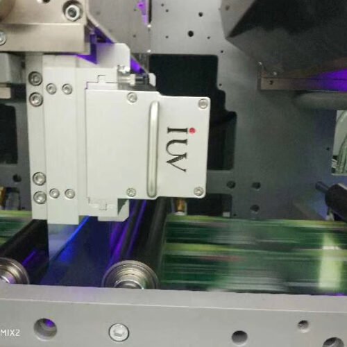
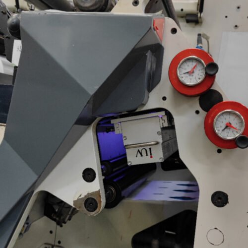
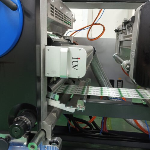
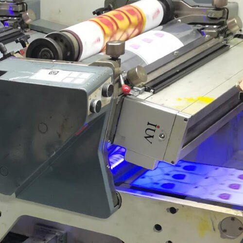
A sheetfed offset press presents different integration constraints from a narrow-web label press. The sheet travels through transfer cylinders, gripper bars, impression nips, and guide surfaces. The LED head must fit into this path without creating collision risk, excessive heat, stray UV exposure, or difficult access for maintenance.
Interdeck Curing Changes the Offset Printing Sequence
In conventional sheetfed offset printing, wet ink layers transfer through successive units before final drying or curing at the delivery. This wet-on-wet sequence supports normal trapping, but it can create problems with high ink coverage, difficult solid colours, long delivery stacks, or sensitive substrates.
Interdeck LED curing allows an earlier image to be stabilised before the next printing unit. The process can reduce ink movement, help hold fine dots, and limit contamination between colours. It may also support cleaner handling of opaque white, dense spot colours, metallic inks, or heavy coating layers.
However, an interdeck unit must be specified for a defined purpose. Pinning, partial cure, and final cure require different exposure levels. A strong cure after an early printing unit may reduce the ability of the following ink to trap correctly. It may also create an overly cured surface that affects adhesion of a later varnish or coating.
The press configuration should therefore identify which printing units need interdeck exposure and why. A four-colour process job may need a different arrangement from a job containing opaque white, a metallic base, or a high-build overprint varnish. The cure sequence should follow the ink stack rather than a fixed rule for every unit.
UV LED Offset Printing Retrofit: Start with the Sheet Path
The first retrofit task is a physical survey of the press. The survey should identify the transfer-cylinder geometry, gripper-bar sweep, maximum sheet thickness, sheet size range, and available space between printing units. The lamp housing must remain clear of every moving part through the full press cycle.
Clearance should be verified for standard paperboard, lightweight paper, metallised stock, synthetic sheets, and any expected curled material. A sheet that lifts slightly from the cylinder can reduce the available lamp clearance. The retrofit design must account for this movement rather than relying only on nominal mechanical drawings.
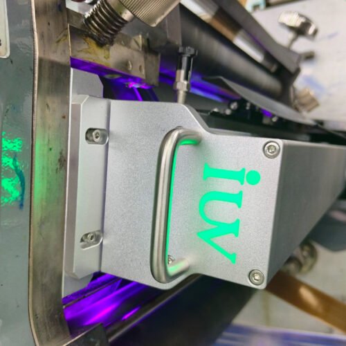
The LED head should illuminate the printed side of the sheet at a controlled distance. It must not interfere with the gripper edge or expose areas where ink can accumulate on machine components. The housing should also avoid creating a sharp air disturbance that affects lightweight sheets during transfer.
Access is another important consideration. Operators need safe access to blankets, plate cylinders, ink rollers, and dampening rollers. A lamp assembly that blocks normal service access can increase maintenance time and encourage unsafe workarounds. Retractable, hinged, or service-position mounting may be required, depending on the press layout.
Optical Geometry Determines Effective Exposure
LED heads are often evaluated by nominal output, but the useful parameter is energy delivered to the printed sheet. Irradiance is the instantaneous optical power at the sheet surface. Energy dose is the total exposure received while the sheet passes through the illuminated zone.
On a sheetfed press, the exposure time depends on press speed and the illuminated length along the sheet path. The transfer-cylinder diameter, lamp position, and distance from the printed surface all influence the actual dose. A small change in lamp-to-sheet distance can change output at the image area and affect edge-to-edge uniformity.
Output should be measured at the intended image plane using a meter suitable for the LED wavelength. A broad-spectrum UV meter may not provide accurate readings for a narrow-band LED source. Measurements should cover the full usable sheet width, including areas near the operator side and drive side.
The optical design should also limit stray light. Uncontrolled UV exposure can cure ink on blankets, rollers, gripper components, or nearby surfaces. This may create cleaning problems, roller contamination, or inconsistent ink transfer. Shields and baffles should protect press components without compromising the required exposure at the sheet surface.
Wavelength Must Match UV Offset Ink Chemistry
Most LED-UV offset systems operate at wavelengths such as 385 nm, 395 nm, or 405 nm. The correct wavelength depends on the photoinitiator package in the UV offset ink, coating, or varnish. A lamp cannot be selected only by its electrical rating or physical fit within the press.
UV offset ink formulated for a broad-spectrum conventional UV source may not cure efficiently under narrow-band LED output. The printed surface may appear dry while the ink film remains undercured beneath the surface. This can lead to poor rub resistance, reduced adhesion, blocking in the delivery stack, or failures during finishing.
The ink supplier should confirm LED compatibility for the intended wavelength, substrate, and curing sequence. Process colours, opaque white, dense black, metallic inks, and coating systems should be assessed separately. Highly pigmented inks can reduce light penetration and often require a different exposure strategy.
Correct wavelength matching helps avoid excessive lamp output. This is important in sheetfed applications because unnecessary energy can raise sheet temperature, affect ink-water balance, and create dimensional changes in lightweight or synthetic sheets.
Protect Ink-Water Balance and Roller Conditions
Sheetfed offset printing depends on a stable balance between ink and fountain solution. An interdeck LED system should not create conditions that disturb that balance. Heat from the lamp housing, reflected energy, or restricted airflow can affect roller temperature and ink rheology near the printing unit.
The lamp position should keep direct radiation away from dampening rollers, ink rollers, and open ink surfaces. Stray exposure can cause ink build-up or premature curing on machine components. This is especially important when the press stops or runs slowly during make-ready.
The retrofit control system should link LED output to press operation. When the press stops, the LED head should reduce output or switch to a safe standby condition. When the press accelerates, the output should follow the validated production recipe. This prevents overexposure of stationary sheets and protects sensitive materials.
Roller temperature should be checked during extended production runs. A press may appear stable during the first few hundred sheets, then show density variation or changes in emulsification as heat accumulates. The interdeck system should be validated over a realistic run length rather than a short demonstration cycle.
Cure Strategy Must Support Trapping and Registration
Interdeck curing can improve the stability of an early ink layer, but excessive cure can reduce wet trapping for the next colour. The correct setting depends on the ink order, solid coverage, and the surface energy of the partially cured ink film.
For example, an opaque white base may need controlled stabilisation before a coloured image is printed over it. A dense black or metallic ink may require partial cure to prevent marking during transfer. A process-colour sequence may need only minimal pinning to preserve normal trapping and dot behaviour.
Registration must be monitored during this work. The lamp assembly, cooling arrangement, and sheet path can influence sheet temperature and transport behaviour. A sheet that absorbs heat may change dimensionally or behave differently on the transfer cylinder. This can appear as a registration issue even when the printing units are mechanically stable.
Validation should include the lightest and heaviest approved substrates, as well as the highest coverage artwork. A job that remains in register on coated paper may respond differently on synthetic stock, metallised paper, or thin board.
Manage Sheet Temperature and Delivery Performance
LED systems reduce the infrared component associated with many conventional UV sources, but the printed sheet can still warm through absorbed optical energy and repeated exposure. The effect is more pronounced with dark solids, thick ink films, flood coatings, and sensitive synthetic materials.
Temperature should be measured at the sheet surface after interdeck exposure and again at the delivery. The delivery stack should also be inspected for blocking, setoff, curl, and trapped heat. A sheet may pass a surface-cure test while still creating problems when stacked under pressure.
Where the sheet temperature becomes excessive, the process should be adjusted through ink compatibility, exposure sequence, lamp output, or cooling design. Raising lamp power is rarely the first solution. A better match between wavelength and ink chemistry may provide the required cure with lower thermal loading.
Cooling airflow should not disturb sheet transport. Directed air can be useful in some configurations, but uncontrolled airflow may affect lightweight sheets and create static-related handling issues. The retrofit design should manage cooling around the LED head while preserving stable sheet transfer.
Electrical Integration and Safety Functions
An interdeck LED retrofit requires a clear electrical integration plan. The curing system should communicate with press start-stop controls, emergency stops, sheet jam detection, guard switches, and fault alarms. The lamp must enter a safe state when the press cannot transport sheets normally.
The control interface should also support repeatable job recipes. A validated job may require specific output levels after selected print units, with different settings for paperboard, plastic sheets, or heavy ink coverage. Operators should be able to select approved recipes without manually rebuilding the curing sequence.
Safety guarding must protect operators from direct UV exposure and reflected light. The design should include access interlocks, status indicators, and documented maintenance procedures. Electrical cabinets, cooling modules, and cable routing should be placed where they can be serviced without interrupting normal press access.
For OEMs, these control functions should be considered part of the machine integration. A curing head that operates independently from press status can create avoidable risk during production interruptions.
Low-Migration and Sensitive Packaging Applications
Low-migration sheetfed offset work requires a controlled system of inks, coatings, substrates, wash-up materials, and curing conditions. LED curing can support these applications when the materials are designed for the process and the operating parameters are documented.
Interdeck curing must be assessed within the complete print stack. A partially cured ink layer may affect the adhesion of later ink or varnish layers. The final cure stage must deliver the performance required for the finished packaging structure, not only for the first cured layer.
Process records should include the ink system, substrate type, lamp wavelength, output settings, press speed, and approved quality tests. Operators should not compensate for a production issue by changing lamp output without reviewing the effect on cure, adhesion, and the relevant packaging requirements.
Maintenance Preserves Interdeck Cure Quality
The LED window is a critical optical surface. Ink mist, powder, paper dust, coating splash, and pressroom contamination can reduce output or create uneven exposure across the sheet. Regular inspection and approved cleaning are necessary to maintain the validated cure condition.
Cooling performance also requires routine checks. Air-cooled systems need clean filters and functional fans. Water-cooled systems need correct flow, fluid condition, hose inspection, and alarm verification. Reduced cooling can affect output stability and component life.
Lamp output should be measured periodically at the sheet plane and compared across the usable width. Results should be trended by curing head. A gradual decline can be corrected before it causes adhesion failures, setoff complaints, or inconsistent colour-to-colour performance.
Troubleshooting Common Retrofit Problems
Poor rub resistance or blocking after an interdeck retrofit may indicate insufficient final cure, an ink-wavelength mismatch, contaminated lamp windows, incorrect working distance, or excessive ink-film thickness. The first checks should focus on measured output, press speed, ink compatibility, and the cure sequence.
Poor trapping after a curing head is installed may indicate excessive interdeck exposure. Review whether the earlier ink layer is being cured beyond the level needed for pinning. Then assess the next ink’s adhesion and trapping behaviour on the partially cured surface.
Registration drift, sheet curl, or unstable transfer can indicate thermal loading or airflow interference. Check sheet temperature, lamp alignment, cooling airflow, transfer-cylinder clearance, and the condition of grippers and guide surfaces. The fault may result from several small changes rather than one major mechanical issue.
A structured diagnosis prevents the retrofit from becoming a series of unrecorded adjustments. It also protects the relationship between press mechanics, offset chemistry, and LED cure performance.
Conclusion
Integrating interdeck LED curing into a sheetfed offset press requires coordinated mechanical, optical, electrical, and process design. The lamp head must fit the sheet path safely, deliver controlled energy at the image surface, and operate in step with the press.
A successful UV LED offset printing retrofit uses interdeck exposure for a defined printing purpose, such as pinning or controlled ink stabilisation. It protects trapping, registration, roller conditions, and delivery performance while providing enough cure for the approved ink system. When the curing sequence is measured, documented, and maintained, interdeck LED curing can become a stable part of sheetfed offset production.